Intel Galileo: Autonomous Navigation Rover with JavaScript
Posted by Rick Waldron
Earlier this year, I published an article that announced support for running Johnny-Five programs directly from an Intel Galileo Generation 2 single board computer. Since then, a lot of work has gone into fine tuning Galileo-IO, including a complete internal redesign that takes advantage of native I/O bindings and processing capability improvements whenever possible. Over the months spent working on this platform, we’ve built relationships with teams at Intel Labs and Intel’s Internet of Things Developer Program. It was through these groups that we were invited to this year’s Intel Developer Forum (IDF), as an exhibitor representing the open source community, along side the team from Octoblu.
The Plan
The project would be to make an autonomous, four-wheeled rover. The rover would be able to detect and avoid obstacles while navigating from one geoposition to another via gps signal. All of this would be controlled by a single JavaScript program, running in a stable Node.js environment, directly on-board the Intel Galileo Generation 2 board. The program would use the Johnny-Five framework to interact with the hardware. I felt confident that this set of capabilities was both impressive and realistically deliverable.
The initial program looks approximately like this:
var five = require("johnny-five");
var board = new five.Board();
board.on("ready", function() {
  // Program robot here.
});
Because Johnny-Five is smart enough to figure out that the program is being run directly from the Galileo itself, the previous code produces the same result as the following:
var Galileo = require("galileo-io");
var five = require("johnny-five");
var board = new five.Board({
  io: new Galileo()
});
board.on("ready", function() {
  // Program robot here.
});
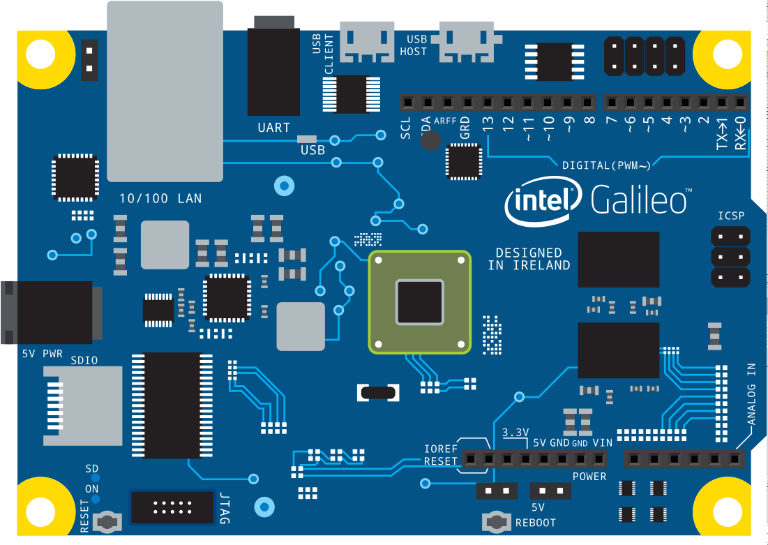
The minimal breadboard view serves as a starting point for the hardware that I’ll introduce as the rover development progresses. Note that the board shown is actually the Galileo Generation 1; at the time of this writing I was unable to find a Generation 2 breadboard image, however the program has been run and confirmed for correctness on both platforms.
Power System
The rover’s power circuit begins with a Turnigy nano-tech 1300mAh 4S 25-50C Lipo pack battery source shared between two battery eliminator circuits: 12V 3A for the Galileo and 6V 3-5A for the servos. To calculate the run time this will provide:
                        1        60 minutes
    1.3 Amp·hours  x  ------  x  ----------  =  26 minutes
                      3 Amps       1 hour
Communication
The Galileo is equipped with a mini-PCI Express slot, so I installed an Intel® Centrino® Advanced-N 6205 coupled with a Half to Full Height Mini PCI Express(PCI-E) Card Bracket Adapter and antenna. Installation instructions are out of scope for this report, however Sergey Malinov published an excellent walk through. During early development, I preferred connecting via ethernet cable and recommend others follow suit; doing so reduces the amount of heat produced by the board while offering a quicker and more readily available connection to the board. For actual test runs, connect to the Galileo via ssh over wlan. (Sublime Text 2 (or greater) users should install rsub, which allows you to open remote files locally, in Sublime Text.)
Locomotion and Chassis
Using only Lego Technic pieces from two combined Lego NXT kits, I framed a rough design for the chassis and locomotion components. The rover’s drive system is composed of a single HSR-1425CR Continuous Rotation Servo, mounted in place with a Hitec Standard Servo Mounting kit. Space and limitations of the servo horn adapter resulted in a 2.25:1 Drive (36 tooth) to Follower (16 tooth) gear ratio for the rear-wheel drive system. The 2.25:1 ratio is inappropriate in that it provides speed over torque—in some cases this is desirable, however this machine as a whole is relatively light and would benefit in surface navigational versatility from greater torque. In simpler terms, with too little torque, the rover would struggle on rough or uneven surfaces.
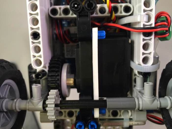
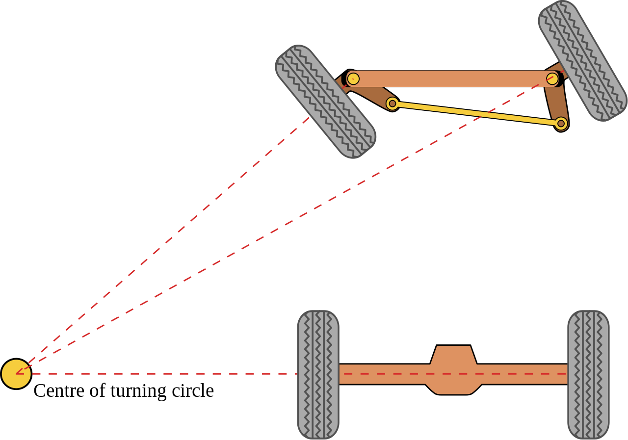
For the steering component, I avoided the common three-wheeled (two drive, one balance) differential-drive system, and instead created an Ackermann-style design. This makes the steering apparatus less central to the overall design, granting me the flexibility needed to craft a non-circular, non-square chassis. This, in turn, results in better maneuverability and stability.
The first steering shaft design was a naively conceived “chain” driven affair with a terrible 2.5:1 ratio (recall the adaptor limitation: 36 and 40 tooth gears). Subsequent iterations resulted in a direct drive arm connected to the drag link. The servo controlling the drive arm is a Hitec HS-5685MH High Voltage, High Torque, Metal Gear Digital Sport Servo, mounted in place with a Hitec Standard Servo Mounting kit
To control the servos, I updated the program to initialize two Servo instance objects, one continuous and one standard:
// Create a continuous servo object
// that's attached to pin 9.
var drive = new five.Servo({
  pin: 9,
  type: "continuous",
});

// Safely assume the following alias definitions:
// drive.fwd() => drive.cw()
// drive.rev() => drive.ccw()

// Create a standard servo object
// that's attached to pin 10. This
// servo is specified to have a limited
// angular range, from 70° to 110°
var steer = new five.Servo({
  pin: 10,
  range: [70, 110],
});

// Turning notes:
// 90° is center
// 70° is left
// 110° is right
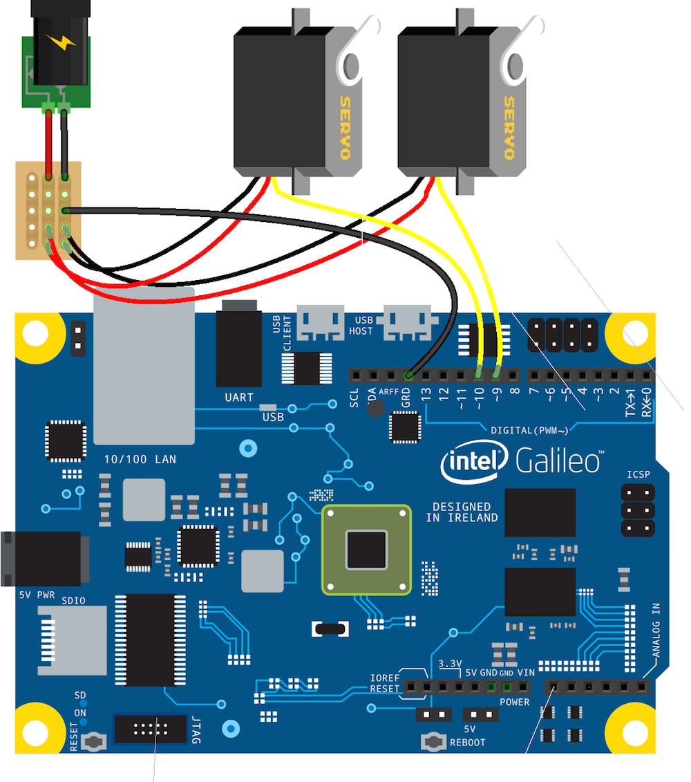
This is the breadboard view updated to include the two servos connected to pins 9 and 10, with an external power source and a common ground line from the source to the Galileo.
The previous portion of the program included comments that listed the steering angles; those three values correspond to the following three images:

Obstacle Avoidance
The obstacle detection and avoidance system is comprised of three Sharp IR Distance/Proximity GP2Y0A02YK0F/0A02 (20 to 150 cm) sensors:
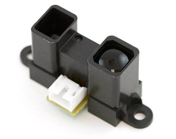
(Click here for details on how these sensors operate)
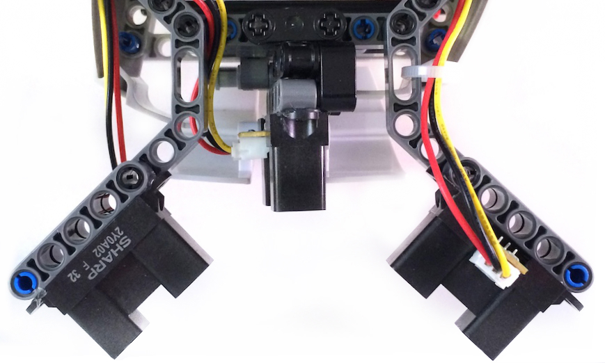
For this machine, the sensors will be arranged such that the left and right sensors cross each other (with a slight height offset) and center sensor will face forward. An earlier configuration had the sensors facing out and away from each other, which produced larger dead zones to the left and right of the middle sensor. Crossing the IR beams, as shown below, reduces the size of those dead zones. (It may be rare in a lot of engineering projects, but in this case it’s actually preferable to cross the streams.)

The left sensor is rotated 180° so that its light emitter and light detector placement matches the sensor on the right, with the emitter on the outer-most edge of the mounting arm.
Introduce the three sensor objects to the program, according to the sensor arrangement shown above:
// `Sampler` is a simple class for maintaining
// a data set of a fixed size. The implementation
// has been omitted for sake of brevity.
var Sampler = require("./sampler");

// Define three direction sensors, with an id, model and
// relevant pin number with 1ms read cycles (only possible
// when running on Intel's IoTKit platform, where platform
// capabilities bindings are present).
var shared = {
  model: "0A02",
  freq: 1
};
var directions = [
  { id: "right", pin: "A0" },
  { id: "front", pin: "A1" },
  { id: "left", pin: "A2" },
];
var sensors = directions.reduce(function(direction, ir) {
  var samepleSize = 5;
  // First, initialize both an IR.Distance object
  // and a corresponding empty `Sampler`. The initial
  // value of the distance reading for each sensor is 0.
  direction[ir.id] = {
    ir: new five.IR.Distance(Object.assign({}, shared, ir)),
    sampler: new Sampler(samepleSize),
    distance: 0,
  };
  // Create an event listener that collects readings
  // and requests an average from the `Sampler` object.
  // `Sampler` objects will only produce a null value
  // until their sampler size has been satisfied.
  direction[ir.id].ir.on("data", function() {
    direction[ir.id].sampler.add(this.inches);

    var average = direction[ir.id].sampler.average();

    // The sample had enough values present
    // to calculate average
    if (average) {
      direction[ir.id].distance = average | 0;
      direction[ir.id].sampler.reset();
    }
  });

  return direction;
}, {});
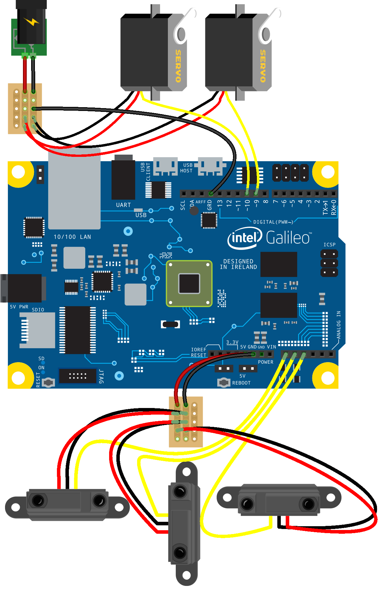
Here’s the updated breadboard view with all three IR sensors attached:
State Machine
Now that I’ve implemented means for both input and output, the next step is to define a simple state machine. “Simple” was the driving factor for deciding which library to use and I ultimately selected Jake Gordon’s javascript-state-machine. The basic machine looks like this:
function complete() {
  machine.isBusy = true;
  // Wait 1s to allow the actuators to
  // to physically complete the navigation
  // before resuming
  temporal.wait(1000, function() {
    machine.isBusy = false;
    machine[machine.movement]();
  });
}
var machine = StateMachine.create({
  initial: "priming",
  events: [
    {
      name: "prime",
      from: "none",
      to: "advancing"
    }, {
      name: "advance",
      from: "*",
      to: "advancing"
    }, {
      name: "reverse",
      from: "*",
      to: "reversing"
    }, {
      name: "turn",
      from: ["advancing", "reversing", "turning"],
      to: "turning"
    }, {
      name: "stop",
      from: "*",
      to: ["advancing", "reversing"]
    }
  ],
  callbacks: {
    // callbacks described in the next code sample
  }
});
The state callbacks look like this:
// priming: The initial state and serves only
// as a navigational no-op while the first set
// of sensor readings are collected.
onpriming: function() {
  // Use the priming state to
  // set up some useful expando properties:
  Object.assign(this, {
    // Set to true if user enters manual control mode
    isManual: false,
    // Set to true if machine is correcting
    isBusy: false,
    // Machine directional state
    movement: "advance",
    // The most recently unsafe direction
    unsafe: null,
    // The rover's speed
    speed: 0.25
    // Steering center angle
    center: 90,
  });
},

// advancing: Move the rover forward, straight.
onenteradvancing: function(event, from, to) {
  // Center the steering servo. Johnny-Five's servo
  // class will automatically calculate the "center"
  // angle based on the explicit upper and lower
  // range angles, or 0 and 180 by default.
  steer.center();

  // Drive the rover forward
  drive.fwd(machine.speed);

  // Update machine motion state
  machine.movement = "advance";
},

// reversing: Move the rover backward, defaults to
// straight but allows an explicit direction.
onenterreversing: function(event, from, to, data) {
  var angle = !data.direction ? machine.center :
    (data.direction === "left" ? steer.range[0] : steer.range[1]);

  // Set the steering angle
  steer.to(angle);

  // Drive the rover backward
  drive.rev(machine.speed);

  // Update machine motion state
  machine.movement = "reverse";

  complete();
},

// turning: Turn left or right, depending on the
// data collected by the sensors.
onenterturning: function(event, from, to, data) {
  // Faster speed, smaller step angle:
  var step = Math.round(scale(machine.speed, 0, 1, 10, 5));
  var min = steer.range[0];
  var max = steer.range[1];

  if (data.direction === "left") {
    step *= -1;
  }
  // Adjust the servo position angle to turn the rover
  steer.to(constrain(steer.angle + step, min, max));

  // Drive forward at the current speed.
  drive.fwd(machine.speed);

  // Remember the currently unsafe path
  machine.unsafe = data.unsafe;

  complete();
}
Now that the states are defined, the program needs a mechanism to asynchronously process distance readings and transition state based on the results of the current environmental data. In other words, it needs to move and avoid obstacles.
// These are const caps only to illustrate a
// "const"-ness about the value.
var UNSAFE_SIDE = 15;
var UNSAFE_FRONT = 20;

// Map all directions to their opposing value.
var opposite = {
  right: "left",
  left: "right",
  advance: "reverse",
  reverse: "advance"
};

// Use `temporal` to create controlled, "event loop/tick" bound
// executions every 5ms; this will provide ~200hz processing
// frequency.
temporal.loop(5, function loop() {
  var direction = "";

  // In manual control mode, no processing is necessary
  if (machine.isManual || machine.isBusy) {
    return;
  }

  // If approaching an obstruction, slow down
  if (sensors.front.distance < UNSAFE_FRONT) {
    machine.speed -= 0.01;
  }

  // If no obstructions within safe distance, speed up
  if (sensors.front.distance > UNSAFE_FRONT) {
    machine.speed += 0.01;
  }

  // Constrain the speed value to a fractional number
  // between 0 and 1.
  machine.speed = constrain(machine.speed, 0, 1);

  // JavaScript State Machine exposes wonderfully named
  // APIs that allow programs to be written in such a
  // way that their intent is completely understandable.
  if (machine.can("turn") || machine.can("reverse")) {
    // This means that the machine is currently in a state
    // that is allowed to enter a _turning_  state.

    if (sensors.left.distance < UNSAFE_SIDE) {
      machine.turn({
        direction: "right",
        unsafe: "left"
      });
      return;
    }

    if (sensors.right.distance < UNSAFE_SIDE) {
      machine.turn({
        direction: "left",
        unsafe: "right"
      });
      return;
    }

    if (sensors.front.distance < UNSAFE_FRONT) {
      // The last unsafe direction is stored to
      // allow making decisions about which way
      // to turn when the readings don't provide
      // an obvious result. When the obstruction
      // is straight ahead, and we know what the
      // last unsafe direction was, get the
      // opposing direction.
      //
      // If no previously unsafe direction is
      // currently known, then pick one at
      // random and go for it.
      //
      // It doesn't matter if either of these are
      // also unsafe, the program will find out
      // soon enough and will correct accordingly.
      direction = machine.unsafe ?
        opposite[machine.unsafe] :
        Math.random(10) * 10 > 5 ? "right" : "left";

      // If the obstruction is distant enough to
      // drive around, transition to a turning state.
      if (sensors.front.distance > UNSAFE_FRONT - 10) {
        machine.turn({
          direction: direction,
          unsafe: machine.unsafe
        });
      } else {
        // If the obstruction is too close, transition
        // to a reversing state, in the "safe" or
        // "random" direction.
        if (machine.can("reverse")) {
          machine.reverse({
            direction: direction
          });
        }
      }
      return;
    }
  } else {
    // Currently turning or reversing and no
    // "turning" state transition was entered.
    if (machine.can("advance")) {
      // Clear the saved unsafe path
      machine.unsafe = null;
      machine.advance();
    }
  }
});
Navigating With GPS
Now that locomotion, obstacle avoidance and state transition processing are implemented, I could focus on implementing navigation from one location to another by latitude and longitude coordinates. To accomplish this, I’ve added an I²C magnetometer compass to track the heading and a GPS Receiver to track the rover’s current position coordinates.
The GPS Receiver is a serial device that receives coordinate data from up to 66 satellites as standard NMEA sentences. To make the data available to the Node.js environment, simply connect the GPS unit’s TX line to the Galileo’s RX0 and the data will stream directly to /dev/ttyS0. To consume this data, I created a simple GPS class that initializes a stream by opening the serial port, creating a read stream, and accumulating the available data chunks until a valid (ie. RMC or GGA) sentence arrives. Once a valid sentence string is collected, it gets parsed using James Penn’s node-nmea module.
var fs = require("fs");
var Emitter = require("events").EventEmitter;
var nmea = require("nmea");
var priv = new WeakMap();

function Coordinates(x, y) {
  this.latitude = x || 0;
  this.longitude = y || 0;
}

function GPS(path) {
  Emitter.call(this);

  var current = new Coordinates();

  var last = new Coordinates();

  var position = new Coordinates();

  priv.set(this, position);

  var handler = function(sentences) {
    var isChange = false;
    var rmc, gga, location, degrees, minutes;

    try {
      // Parse both sentences and combine the
      // results into a single location object
      gga = nmea.parse(sentences.GGA);
      rmc = nmea.parse(sentences.RMC);
      location = Object.assign({}, gga, rmc);
    } catch (e) {
      return;
    }

    // Compute the decimal value from the
    // resultant lat, lon properties

    degrees = location.lat.slice(0, 2);
    minutes = location.lat.slice(2) / 60;

    lat = +(parseFloat(degrees) + parseFloat(minutes)).toFixed(6);

    // Compute the latitude sign if necessary
    if (location.latPole === "S") {
      lat *= -1;
    }

    degrees = location.lon.slice(0, 3);
    minutes = location.lon.slice(3) / 60;

    lon = +(parseFloat(degrees) + parseFloat(minutes)).toFixed(6);

    // Compute the longitude sign if necessary
    if (location.lonPole === "W") {
      lon *= -1;
    }

    if (!Number.isNaN(lat) && last.latitude !== lat) {
      isChange = true;
    }

    if (!Number.isNaN(lon) && last.longitude !== lon) {
      isChange = true;
    }

    var coordinates = new Coordinates(lat, lon);

    var arg = {};

    // Merge the final lat/lon values, with the parsed
    // nmea data object, into a fresh data object.
    Object.assign(arg, location, coordinates);

    // Update the privately stored position data object
    Object.assign(position, coordinates);

    // The previous lat and lon were 0,
    // but the current lat and lon are
    // valid decimal value coordinates.
    // This indicates a satellite fix
    if (!last.latitude && lat &&
        !last.longitude && lon) {
      this.emit("satellite-fix");
    }

    // The previous lat and lon were 0,
    // but the current lat and lon are 0.
    // This indicates loss of satellite fix
    if (last.latitude && !lat &&
        last.longitude && !lon) {
      this.emit("satellite-lost");
    }

    if (isChange) {
      this.emit("change", arg);
    }

    this.emit("data", arg);

    last.latitude = lat;
    last.longitude = lon;
  }.bind(this);

  fs.open(path, "r+", function(err, fd) {

    var data = "";
    var sentences = {
      GGA: "",
      RMC: ""
    };

    if (!err) {
      fs.createReadStream(path, {
        fd: fd, encoding: "utf8"
      }).on("data", function(chunk) {
        var length = chunk.length;

        for (var i = 0; i < length; i++) {
          data += chunk[i];

          // Newline indicates end of a sentence
          if (data.endsWith("n")) {
            // Process only the sentence types that we care about:
            //
            //    RMC
            //    http://www.gpsinformation.org/dale/nmea.htm#rmc
            //
            //    GGA
            //    http://www.gpsinformation.org/dale/nmea.htm#gga
            //
            if (data.startsWith("$GPRMC")) {
              sentences.RMC = data;
            }

            if (data.startsWith("$GPGGA")) {
              sentences.GGA = data;
            }

            // Once both sentences are captured, the
            // cycle is complete. Send along a copy of
            // captured sentences and reset capture strings.
            if (sentences.GGA && sentences.RMC) {
              handler(Object.assign({}, sentences));
              sentences.GGA = "";
              sentences.RMC = "";
            }

            data = "";
          }
        }
      });
    }
  });
}

GPS.prototype = Object.create(Emitter.prototype, {
  constructor: {
    value: GPS
  }
});

var DEG_TO_RAD = Math.PI / 180;
var RAD_TO_DEG = 180 / Math.PI;
var TAU = Math.PI * 2;

function radians(deg) {
  return deg * DEG_TO_RAD;
}

function degrees(rad) {
  return rad * RAD_TO_DEG;
}

function sq(val) {
  return val * val;
}

// Replace with destructuring
var sin = Math.sin;
var cos = Math.cos;
var atan2 = Math.atan2;
var sqrt = Math.sqrt;

function courseTo(lat1, long1, lat2, long2) {
  // Ported from TinyGPS
  var dlon = radians(long2 - long1);
  lat1 = radians(lat1);
  lat2 = radians(lat2);
  var a1 = sin(dlon) * cos(lat2);
  var a2 = sin(lat1) * cos(lat2) * cos(dlon);
  a2 = cos(lat1) * sin(lat2) - a2;
  a2 = atan2(a1, a2);
  if (a2 < 0) {
    a2 += TAU;
  }
  return degrees(a2);
}

function cardinal(course) {
  // Ported from TinyGPS
  var directions = [
    "N", "NNE", "NE", "ENE", "E", "ESE", "SE", "SSE",
    "S", "SSW", "SW", "WSW", "W", "WNW", "NW", "NNW"
  ];
  var direction = ((course + 11.25) / 22.5) | 0;
  return directions[direction % 16];
}

function distanceBetween(lat1, long1, lat2, long2) {
  // Ported from TinyGPS
  var delta = radians(long1 - long2);
  var sdlong = sin(delta);
  var cdlong = cos(delta);
  lat1 = radians(lat1);
  lat2 = radians(lat2);
  var slat1 = sin(lat1);
  var clat1 = cos(lat1);
  var slat2 = sin(lat2);
  var clat2 = cos(lat2);
  delta = (clat1 * slat2) - (slat1 * clat2 * cdlong);
  delta = sq(delta);
  delta += sq(clat2 * sdlong);
  delta = sqrt(delta);
  var denom = (slat1 * slat2) + (clat1 * clat2 * cdlong);
  delta = atan2(delta, denom);
  return delta * 6372795;
}

GPS.cardinal = cardinal;
GPS.courseTo = courseTo;
GPS.distanceBetween = distanceBetween;

GPS.prototype.courseTo = function(lat, lon) {
  var state = priv.get(this);
  return courseTo(state.latitude, state.longitude, lat, lon);
};

GPS.prototype.distanceBetween = function(lat, lon) {
  var state = priv.get(this);
  return distanceBetween(
    state.latitude, state.longitude, lat, lon
  );
};

module.exports = GPS;
Back in the rover program code, I made sure to add an appropriate var GPS = require("./gps"); at the top, and then in the body of the program:
var gps = new GPS("/dev/ttyS0");
// This is an illustrative substitute for an
// operator entered destination coordinate set:
var dest = {
  latitude: 40.704294,
  longitude: -73.994798
};
Before introducing the turn-by-turn navigation code, the rover will need a compass device to track its own heading. I had a Triple Axis Magnetometer (HMC5883L) available, so this device was used.
var compass = new five.Compass({
  model: "HMC5883L"
});
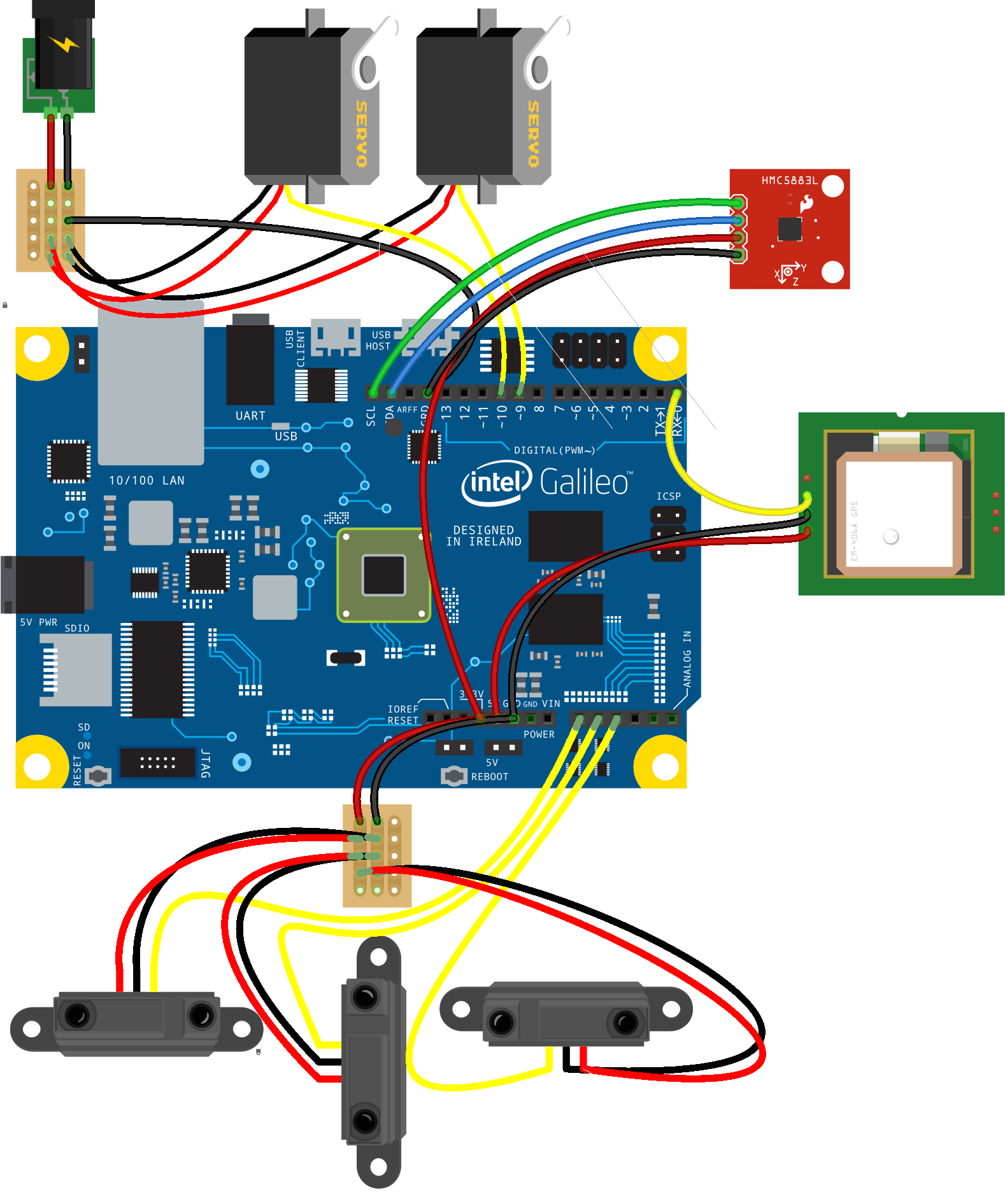
This is the last update to the breadboard view, adding both the compass and GPS components:
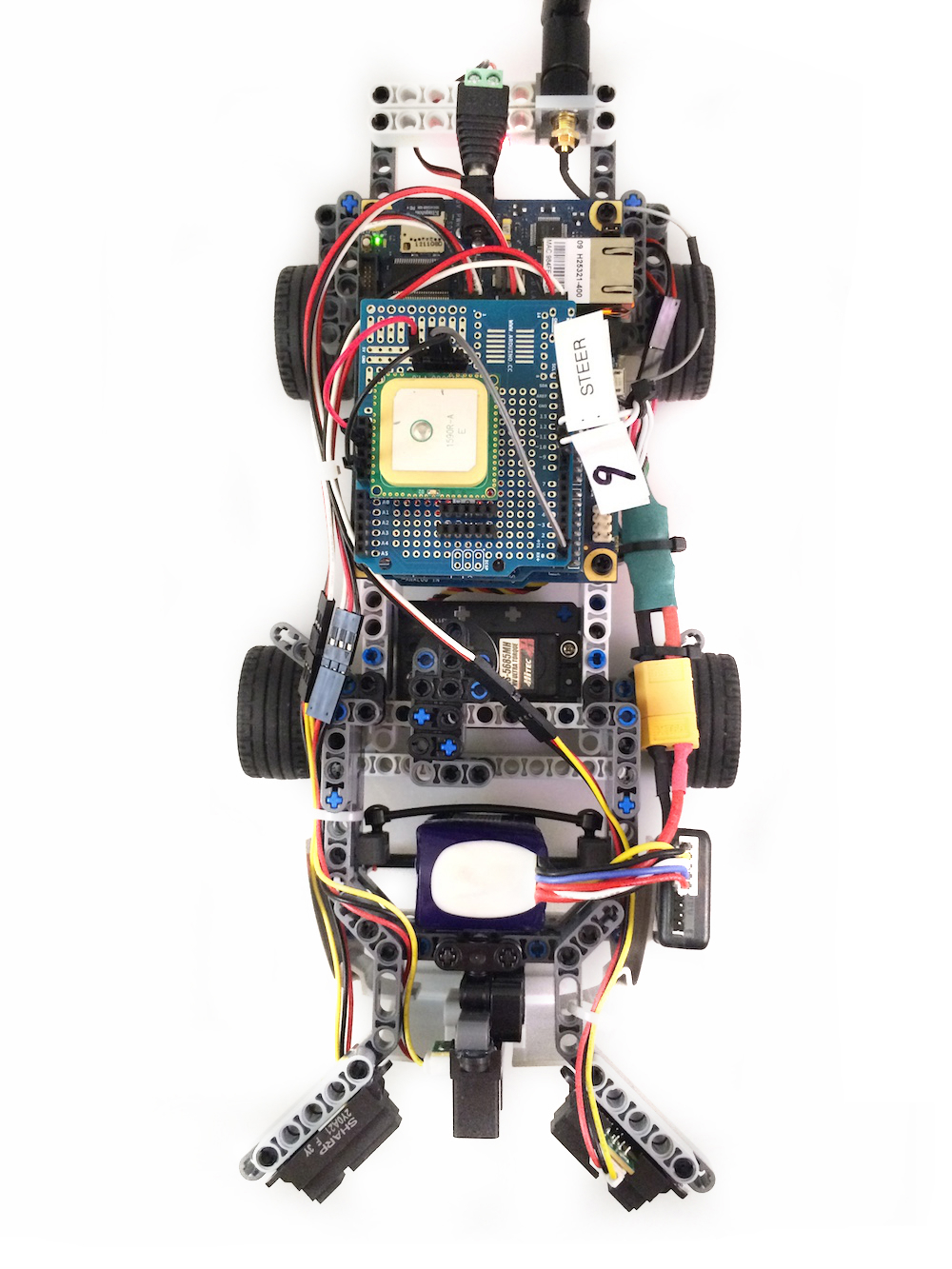
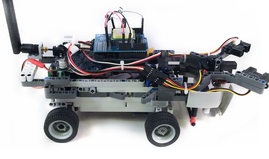
And here are the components as mounted on the rover itself:

The turn-by-turn logic will first calculate the course (in degrees) from the current position coordinates to the destination position coordinates. That value, and the current heading from the compass, will be used to calculate the correction heading. Based on the chart above, assume that 0 is always straight ahead for the rover:
- If the correction heading is within 345-15°, the rover continues straight,
- If the correction heading is within 15-105°, the rover must turn right.
- If the correction heading is within 255-345°, the rover must turn left.
- If the correction heading is within 105-255°, the rover must turn around.
gps.on("change", function() {

  // Defer control to the obstacle avoidance system
  if (machine.isManual || machine.isBusy) {
    return;
  }

  var bearing = gps.courseTo(dest.latitude, dest.longitude);
  var heading = ((360 + bearing - compass.heading) % 360) | 0;
  var direction;

  if (heading >= 345 || heading <= 15) {
    machine.advance();
    return;
  }
  if (heading >= 255 && heading < 345) {
    machine.turn({
      direction: "left"
    });
    return;
  }
  if (heading <= 105 && heading > 15) {
    machine.turn({
      direction: "right"
    });
    return;
  }
  if (heading > 105 && heading < 255) {
    direction = machine.unsafe ?
      opposite[machine.unsafe] :
      Math.random(10) * 10 > 5 ? "right" : "left";

    machine.turn({
      direction: direction,
      unsafe: machine.unsafe
    });
    return;
  }
});
This chart illustrates how the turn-by-turn instructions (as state events) will be computed:
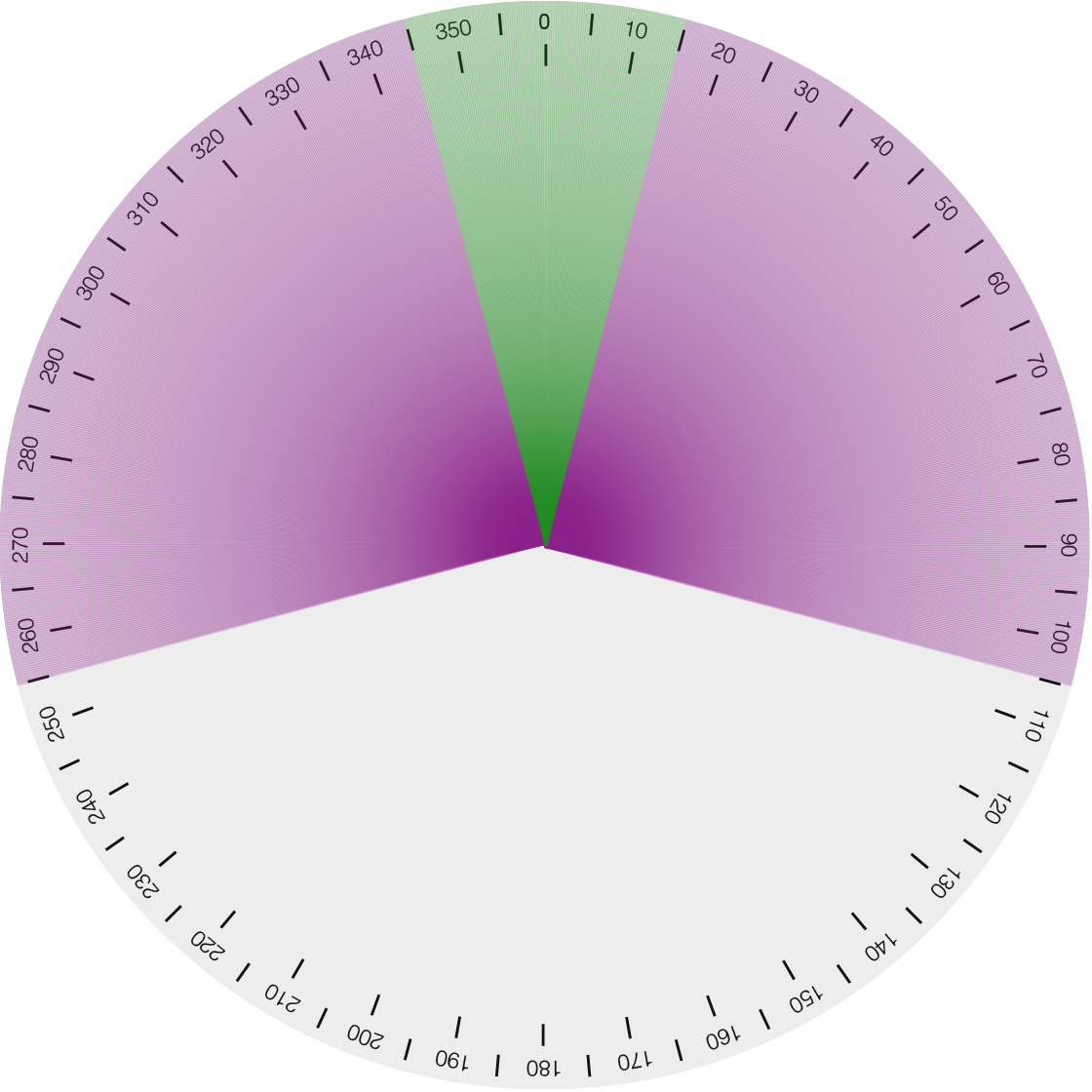
These angles were determined by observing the horn angle of a servo protractor with a mounted compass (the same used in the rover), while orienting myself toward the Brooklyn Bridge.
The GPS data handler is invoked to process changes in the latitude/longitude coordinates as they are received, but will defer control of the rover to either manual control mode or the obstacle avoidance system. Turn-by-turn navigation can make course corrections as needed, as long as the travel way is unimpeded.
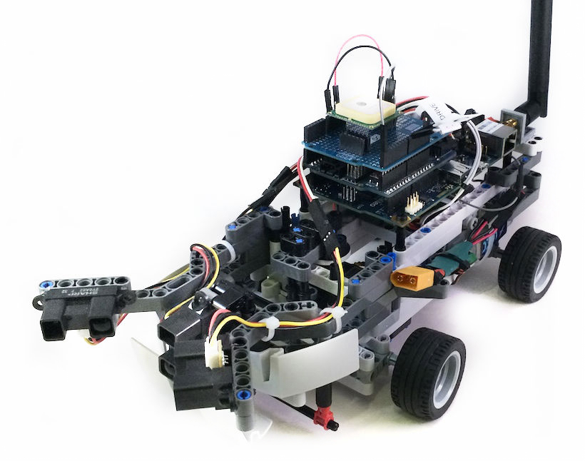
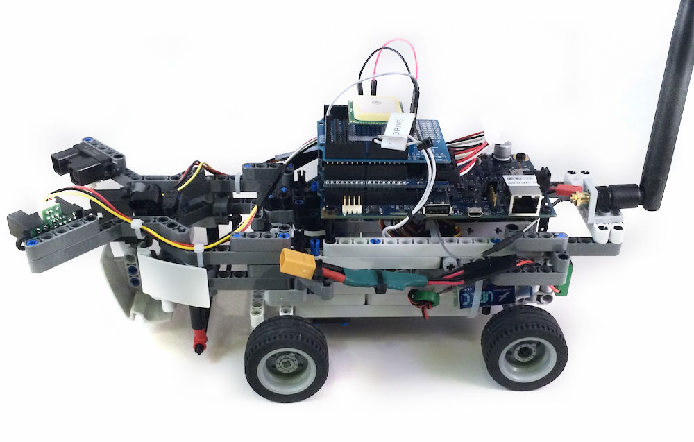
Here is a gallery of images documenting the final form of this iteration of the rover project:

Exploring JavaScript’s Place in Robotics
The purpose of my work on Johnny-Five has never been to prove that JavaScript is necessarily better for robotics programming, but more realistically that it’s capable. Through the development of exploratory projects like this and others, the evidence in support of this continues to grow.