Assembling and Preparing the RobotsConf Sumobot with Johnny-Five
Posted by Rick Waldron
At this year’s RobotsConf, the theme of the event was “Everyone Builds a Robot”. Creator and curator Chris Williams facilitated this by including a SumoBot Kit (designed and produced by Paweł Szymczykowski) and an ARDX Starter Kit for Arduino in the “swag bag” that every attendee received at registration. The bag also included an Arduino Uno and an Electric Imp; a Spark Core was shipped to attendees prior to the conference. (The conference also had Intel Edison, BeagleBone Black and Raspberry Pi boards on hand, but this article will focus on the boards that everyone received.)
In this article, I’m going to walk through preparing, assembling, programming and customizing the same SumoBot that all attendees received. I will also show how to control the bot with all three of the boards mentioned above.
Board Selection
Selecting the controller board that’s right for the project is one of the most important aspects of any robotics or IoT project. Common things to consider include:
- Connectivity: Wi-Fi, Bluetooth, or Serial port.
- Pin Capabilities: digital IO, ADC or PWM.
- Power specifications: Logic level, VIN, VCC, and Voltage Regulation.
- Form factor: board dimensions and footprint.
For the SumoBot’s most basic form, I’m only interested in the pin capabilities. The bot is driven and navigated via a differential drive system comprised of 2 continuous servos, which means that we need at least 2 PWM capable pins.
The customizations I’ll add will require the following hardware from ARDX kit:
- A Photo resistor (light sensor) that requires 1 Analog IO (ADC) capable pin.
- (1) 10KΩ resistor
- Two LEDs that require 1 Digital IO capable pin, each.
- (1) Green
- (1) Red
The following table illustrates the pin capabilities of each board that I have available. It’s clear that they are all adequately qualified for the project.
| Board | # Pins | # Digital IO | # Analog IO | # PWM |
|---|---|---|---|---|
| Arduino Uno | 20 | 14 | 6 | 6 |
| Electric Imp | 6 | 6 | 6 | 6 |
| Spark Core | 16 | 16 | 8 | 8 |
Inventory
The SumoBot Kit comes with an insert that features a complete inventory list for the items in the kit itself, however there a few add-on items that I’ll use which are sourced from the ARDX Kit. Additionally, each item is accompanied by an explanation.
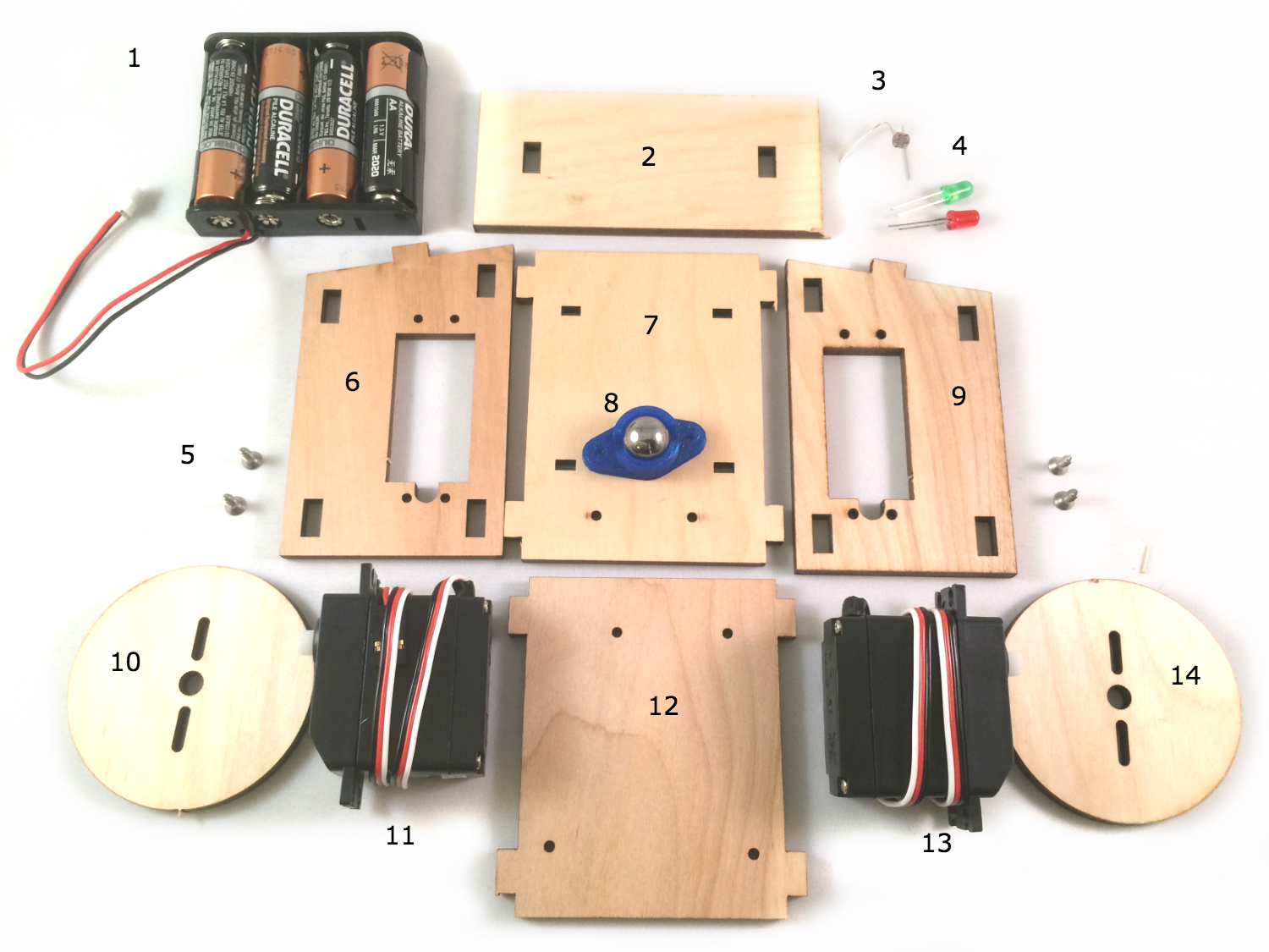
- Battery box with 4 AA batteries. A single AA battery provides a
1.5Vsource, delivered at700mA; when connected in series, 4 AA batteries provide6V, delivered at700mA. All three of the boards can operate with6V; the Electric Imp and Spark Core will regulate to3.3Vand the Arduino Uno will regulate to5V. The servos included in the kit operate at6V. - Front panel
- Photoresistor, or light sensor. This can be sourced from the ARDX Kit and will be used in a later customization of the bot.
- LEDs: one green and one red. These are sourced from the ARDX Kit and will be used in a later customization of the bot.
- Screws; the kit provides 6 and the build will use 2 on each side to secure the servo to the body. The remaining 2 will be used in the Arduino Uno build to fasten the board to the solderless breadboard for that build.
- Left panel
- Bottom panel
- Ball caster; used in this build as the “back wheel” to support the rear of the bot.
- Right panel
- Left wheel
- Left servo
- Top panel
- Right servo
- Right wheel
Preparation
Before proceeding to the assembly step, there are three major preparatory tasks that must be completed. Consider the project blocked until these tasks are complete.
1. Start a project directory, install Node.js modules from npm.
npm init(complete the initialization)npm install johnny-five- Install board-specific IO Plugin.
- If using Arduino Uno: nothing further.
- If using Electric Imp:
npm install imp-io - If using Spark Core:
npm install spark-io,npm install -g spark-cli
2. Setup and connection of controller board.
Arduino Uno. This is the easiest of all three and most recommended for beginners (a 10′ or longer USB Type-B is recommended for the most fun).
- Download the Arduino IDE, version 1.0.6 or newer.
- Connect the Arduino Uno to your laptop with the USB Type-B cable provided in the ARDX Kit.
- Once the software is open:
- Click Tools -> Board -> Arduino Uno
- Click Tools -> Serial Port -> [[The Port]]
- [[The Port]] will appear differently per system:
- Windows:
COM+ a number, eg.COM1 - Linux:
/dev/ttyACM+ a number, eg./dev/ttyACM0 - Mac:
/dev/tty.usbmodem+ a number, eg./dev/tty.usbmodem1411
- Windows:
- [[The Port]] will appear differently per system:
- Click File -> Examples -> Firmata -> StandardFirmata
- Click the Upload icon (a rightward pointing arrow in a circle).
- Once complete, close Arduino IDE, there will be no further need to use it. Do not disconnect the USB cable.
Electric Imp (requires Internet connected Wi-Fi)
- Follow the Developer Kit Quickstart Guide, but skip step 10 where you are instructed to write your own agent and device “Hello World” code.
- Once a new model is created (named “sumobot”), complete the following two copy/paste tasks:
- In the Agent pane, paste the Agent.nut from the Tyrion firmware.
- In the Device pane, paste the Device.nut from the Tyrion firmware
- Under Active Models in the right-hand menu, click the gear icon next to the name sumobot. This will open a dialog that displays a url as: “External URL:
https://agent.electricimp.com/ + agent id“. Copy the device/agent id, which would be “AiZwOE1234567” in this case.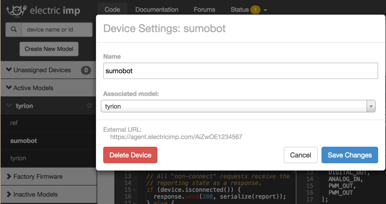
- Paste the id somewhere until it’s time to use it.
- Close the Electric Imp IDE, there will be no further need to use it. (Note: Work is underway to allow remotely flashing the firmware via a CLI program, similar to the
spark-clisetup.)
Spark Core (requires Internet connected Wi-Fi)
spark setup: this process will set up an account and claim the Spark Core. (More commands and information available here: spark-cli)spark flash REPLACE_WITH_DEVICE_ID voodoo: this will flash the VoodooSpark firmware to the Spark Core with the provided device id. The built-in LED will flash magenta during the upload.- Once flashing is complete (as indicated by the built-in LED pulsing cyan), this terminal can closed.
3. Calibrate the Continuous Servos.
Missing or skipping this step is a direct path to failure.
When a continuous servo’s idle pulse is not calibrated to the available PWM range of the controller board, its behavior will be erratic and uncontrollable. Calibration is simple: send the known idle pulse to the servo and adjust the built-in potentiometer until the servo horn comes to a complete stop. If the servo is not moving when the idle pulse is written to the servo, then it’s safe to assume that the servo is already calibrated. To confirm, adjust the built-in potentiometer in clock-wise and counter clock-wise directions; the horn should respond by turning in the corresponding direction.
To calibrate the servos that came with the SumoBot kit, create a new file called calibrate.js containing the appropriate program for the controller board you’re setting up, from the programs shown below. Each program is semantically the same, differing only in details pertaining to which board is being controlled. The purpose of the program is to connect to the board, initialize a continuous servo instance with the Servo.Continuous class and immediately call the instance’s stop method (which will send the idle pulse to the servo)
Arduino Uno
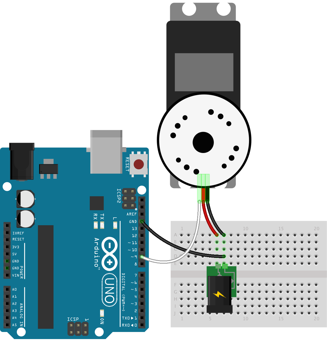
var five = require("johnny-five");
var board = new five.Board();
board.on("ready", function() {
  new five.Servo.Continuous(9).stop();
});
Electric Imp

var five = require("johnny-five");
var imp = require("imp-io");
var board = new five.Board({
  io: new Imp({
    agent: "agent id"
  })
});
board.on("ready", function() {
  new five.Servo.Continuous(9).stop();
});
Spark Core
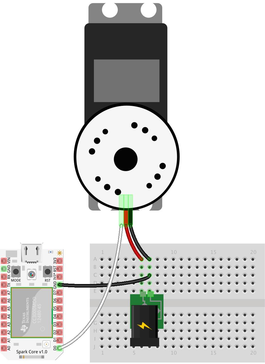
var five = require("johnny-five");
var Spark = require("spark-io");
var board = new five.Board({
  io: new Spark({
    token: "token",
    deviceId: "device id"
  })
});
board.on("ready", function() {
  new five.Servo.Continuous("D0").stop();
});
Run the program with the following:
node calibrate.js
While running, adjust the servo’s potentiometer until it comes to a complete stop. This video shows the operation in action:
Assembly
The SumoBot Kit includes an insert that provides a numbered and illustrated assembly guide; while the guide is adequate, this build is different enough to warrant its own set of instructions.
- For each side panel, line up a servo so that the horn is closest to the front of that panel. The end of the servo with the wiring harness must be opposite of the cut out notch in the panel that would logically be used to thread the wiring through (which is facing to the back of the bot), but this build ignores that logic 😉
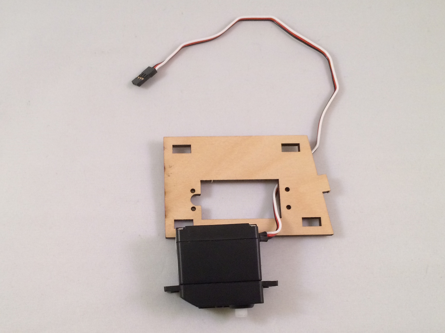
- Push the servo through the mounting cut-out and line up its mounting tabs with the through holes in the side panel
- This is what correctly assembled right and left panels look like:

- Lay out the (clockwise) bottom, right, top and left panels as shown here:
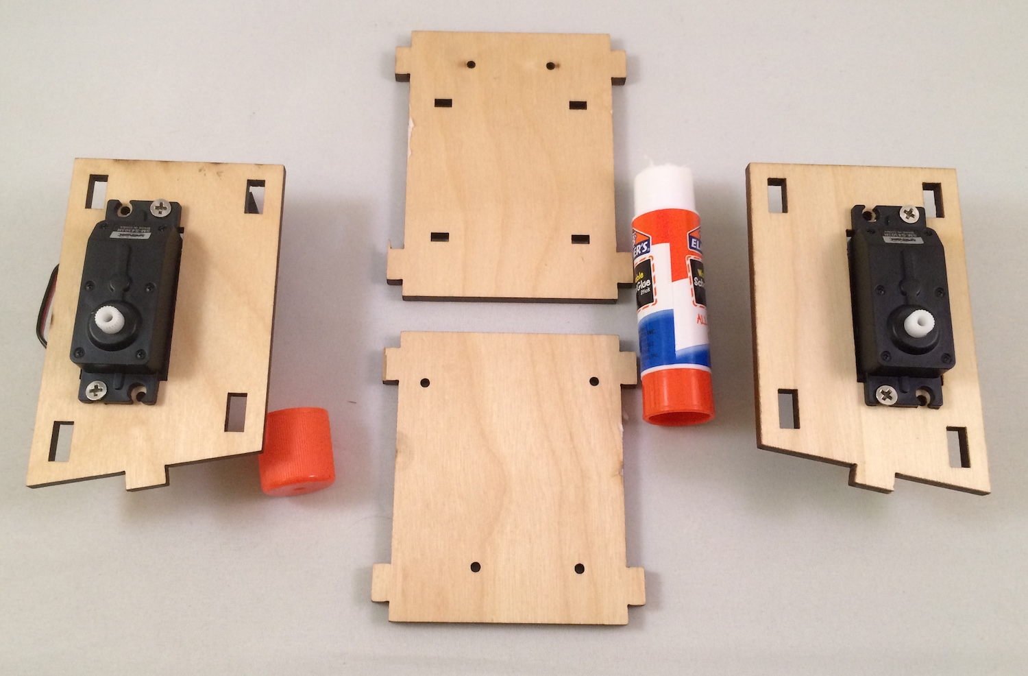
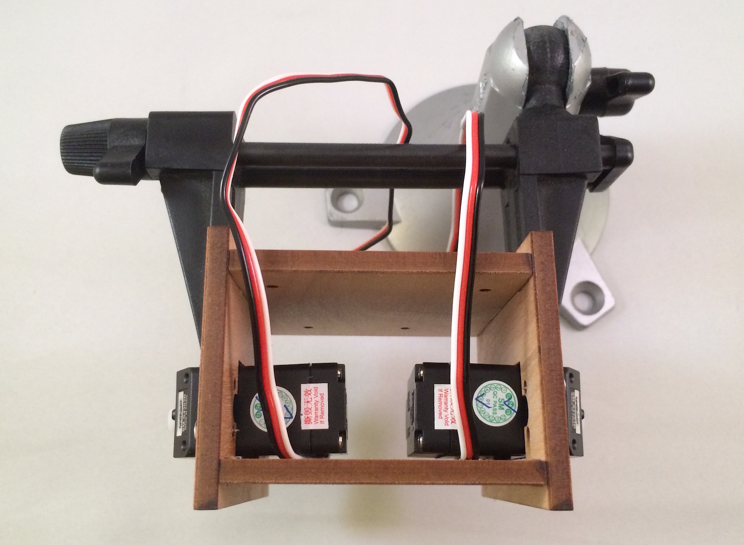
Using a bit of glue at each seam, combine the panels so that they match the following. (Note that the ball caster screws should be in the rear of the assembled bot.)

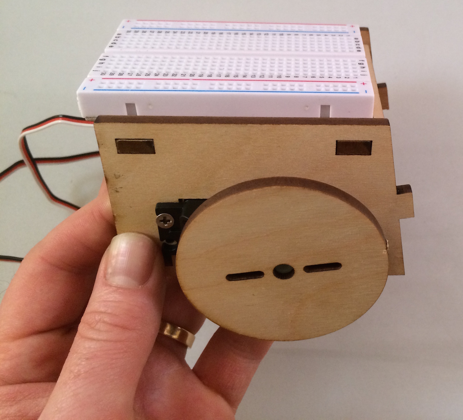
Using adequate force, push the wheels onto the servo horns. Notice that the wheels are notched to match the servo horn.
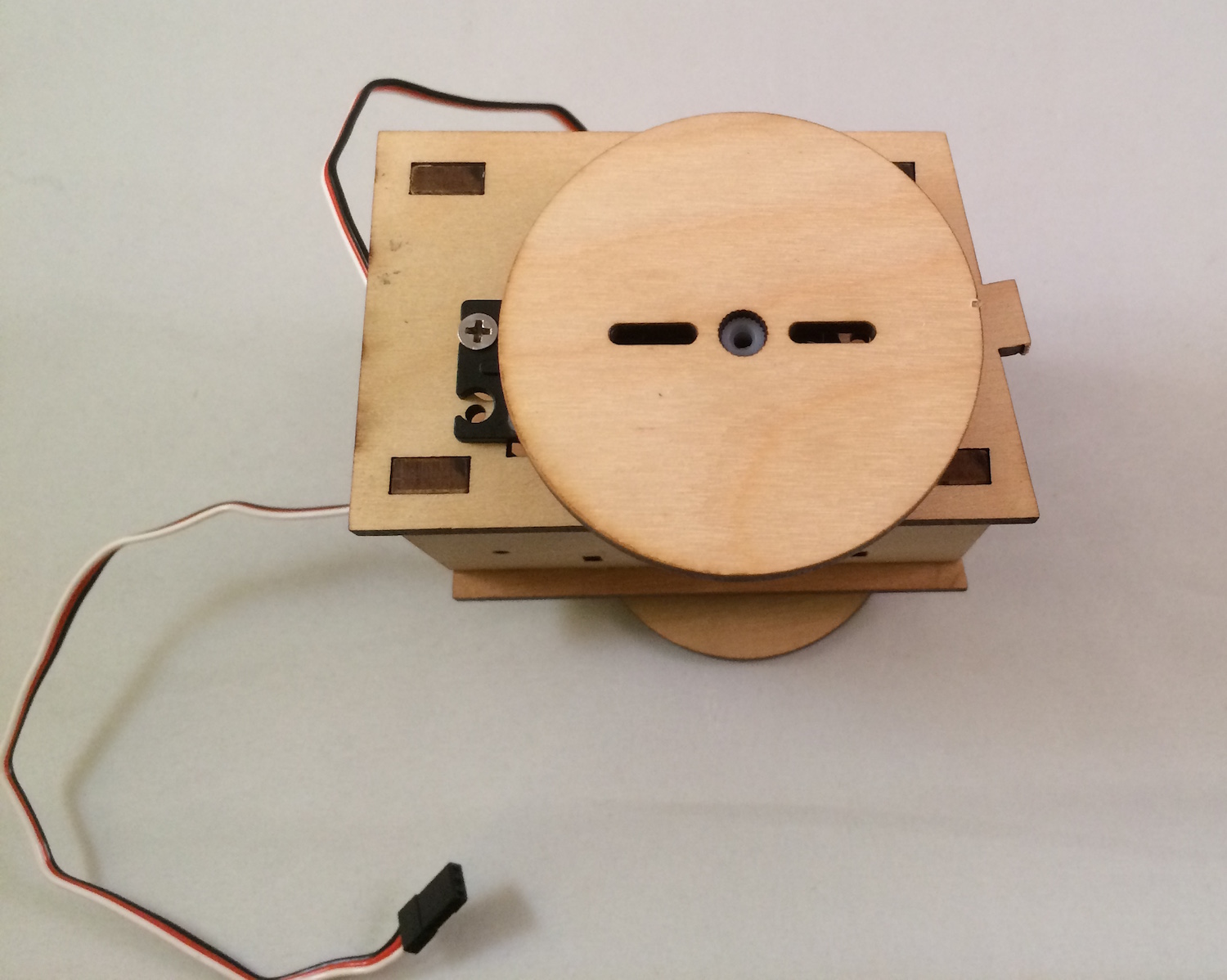

With two screws from one of the servo accessory bags, screw the ballcaster into the bottom panel:
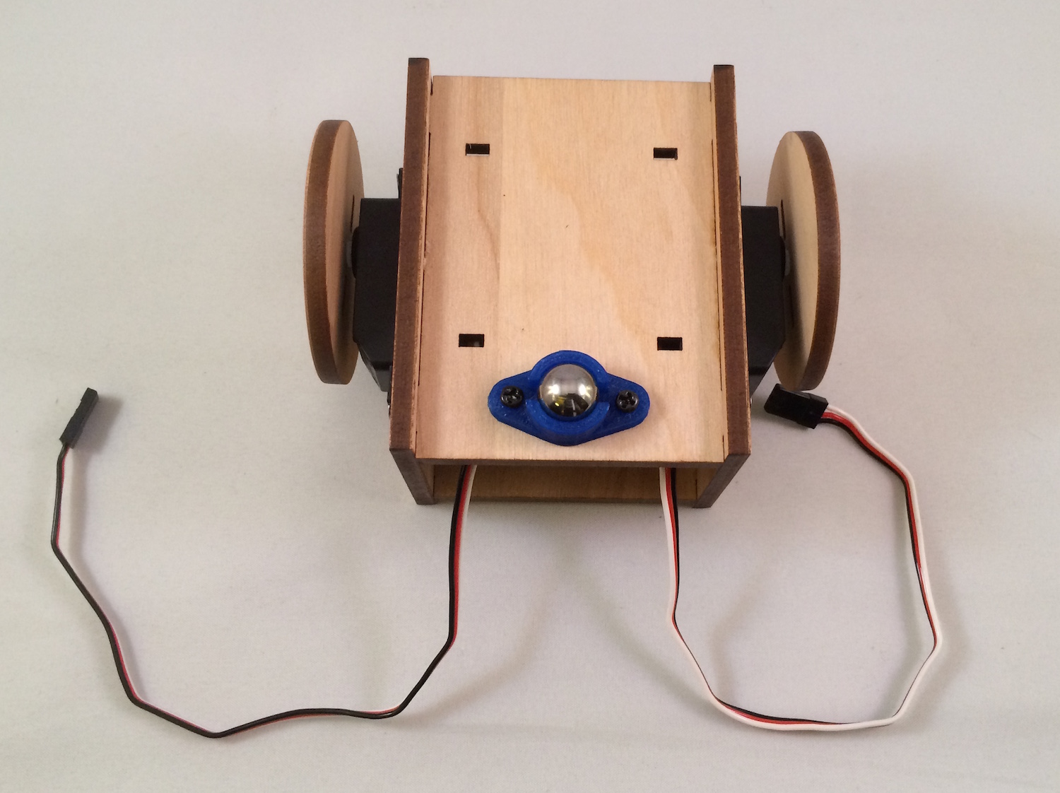
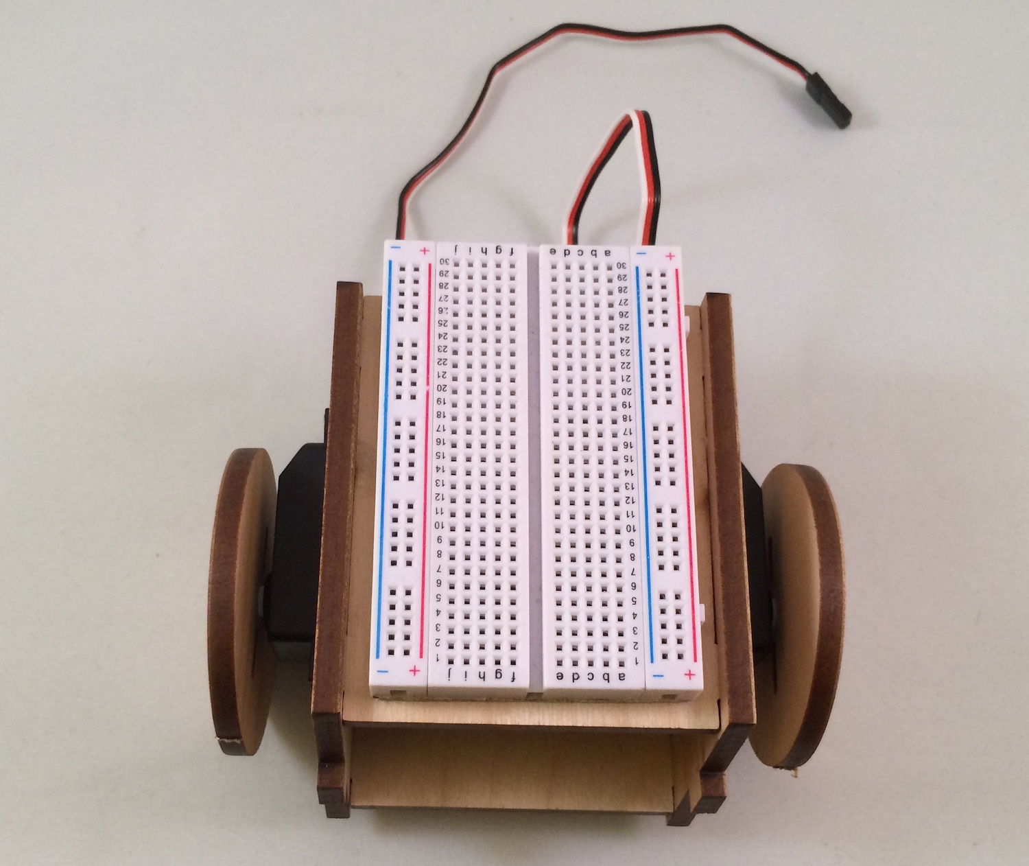
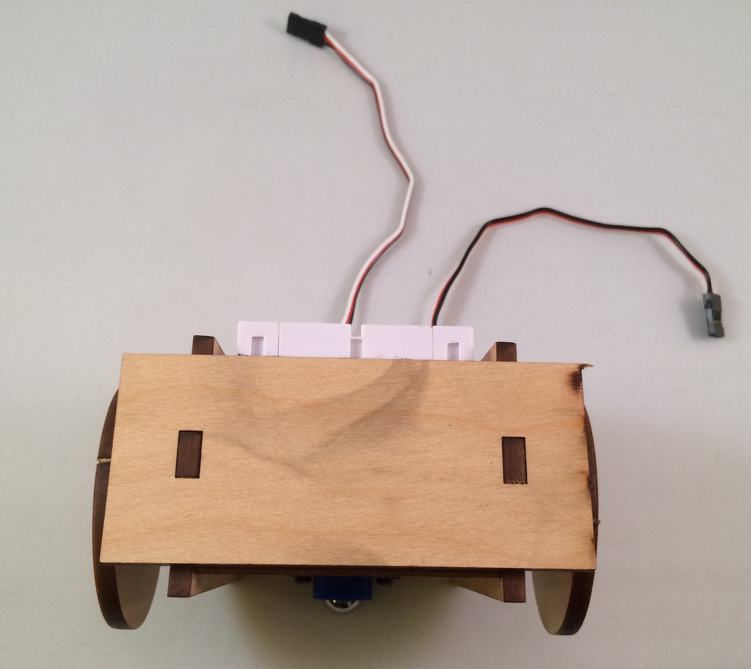
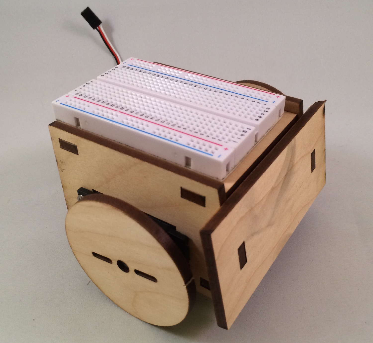
Remove the adhesive backing from the solderless breadboard and attach it directly to the top of the bot:
Attach the front panel to the bot (glue is optional, as you may want to customize this later).
Enjoy your assembled bot!
Next Steps
Over the next three articles, I will show how to use the Electric Imp, Arduino Uno and Spark Core boards as controllers for the now assembled bot.